Making the World’s First Aluminum Xbox Series X
I’m really excited to share this project with the world! I do believe it is the first Aluminum Xbox Series X. This project was quite the undertaking machining wise and will likely be so for awhile.
The XSX design is really simple; it’s literally a rectangle. So, the thought occurred one Sunday while watching the Vikings play what if we machined out a billet Aluminum case? Would any one be interested or even go the extra mile become viral? Well, so far the answer is no, but hopefully someday. Before it could anything I needed to get the XSX. I hadn’t bothered getting one at the time because they were unobtainum. They were constantly sold out, however, I was fortunate enough to find someone selling a brand new in box unit for MSRP + Tax price locally. The total was $550.
Thankfully, I was able to buy 6 in x 6 in billet Aluminum from a local place (Coremark Metals) with no length requirement. So, I bought a 14 inch length for $170.
Taking apart a brand new Xbox was an interesting feeling. I was able to play through most of Halo 5 on it before tearing it down, but it was still only a few weeks old. The tear down was not terribly hard. Most of the screws were hidden behind something like stickers on the back or the bottom disk. In fact, removing the bottom disk was the most difficult part of disassembly. I think the tolerances for the clips were a bit over as it was nearly pressed fit in there. I had to use a screwdriver to push against it while twisting. The rest was easy enough. There is multiple plastic parts that hold the buttons, USB, and Bluray drive that required some careful prying as they were glued down.
Redesigning the case was really straightforward. I took the opportunity to a small redesign and improvement of the bottom. I got rid of the bottom disk and instead designing built in circular feet and added additional holes.
At first I was going to reuse the stock back panel, but I decided against it. It would have required some special slot milling for the lip of the panel to slide in and likely some clipping of the clips. Instead, I designed an all new back panel with custom hole patterns and additional holes going up along the aluminum encasing the XSX boards. Improving thermals was never a goal, but I did take the opportunity to potentially help improve airflow.
The top is very much like the stock XSX with it’s 144 holes and curved cut out. I did my best to recreate this feature. That being said, I’m not quite sure how a draw such a perfect circular yet square cutout. I ended up just doing a draft cut between a small circle and square and then use a big radius fillet on the edges. It’s nearly the same.
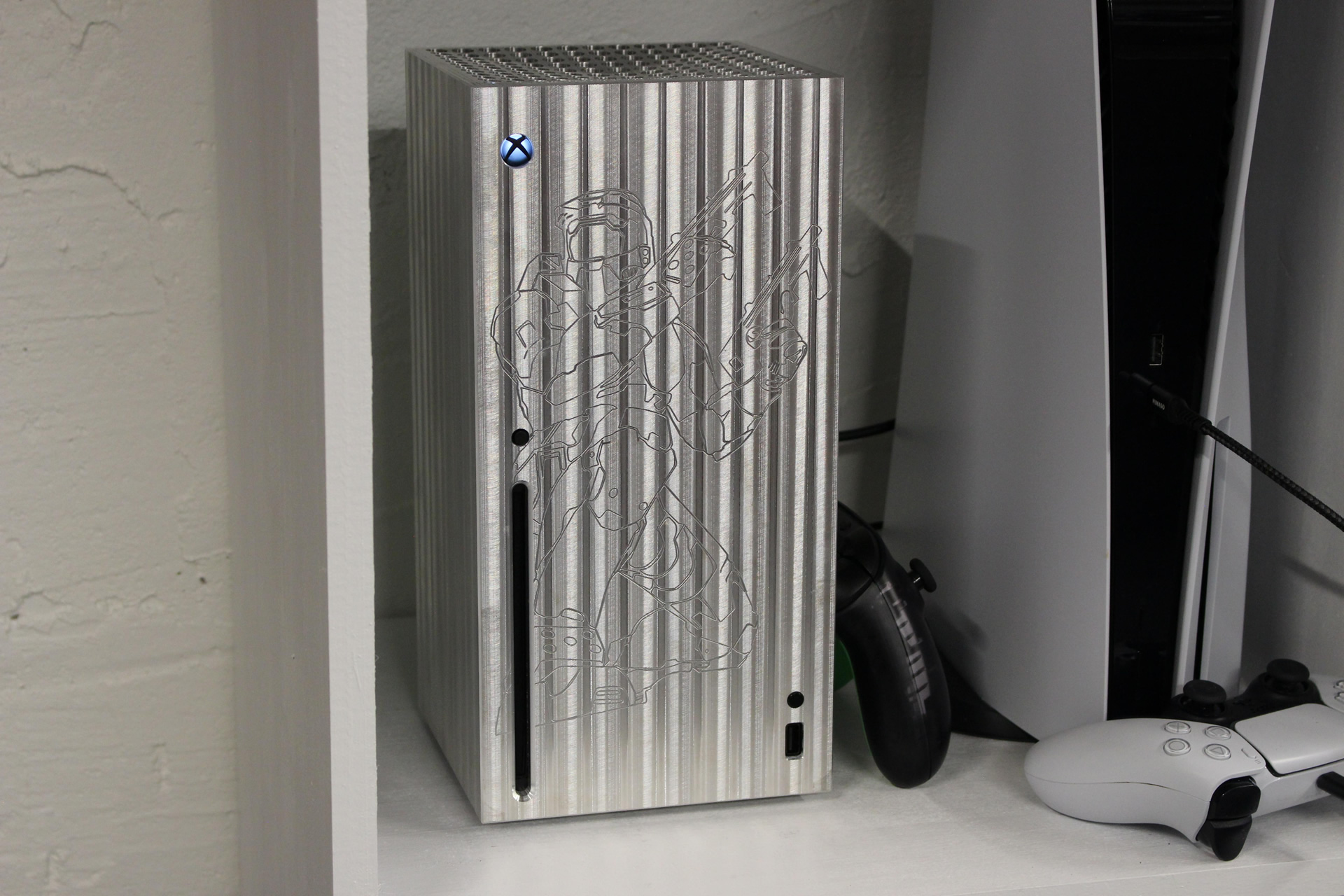
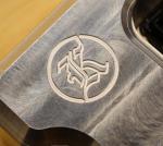
The front didn’t change much other than I took all that blank space and engraved the Master Chief from Halo 2. It’s so much easier said then done, I spent over a full day creating a useable DXF file from the Halo artwork. Then when I went to use the DXF file in Autodesk Fusion 360, there was just too many lines and nodes and it would crash. I ended up importing it in Solidworks, creating my feature on a sheet of the same size in Fusion, and exporting that 3D file into Fusion to create a CAM program. The program for the engraving was separate from the other program.
Having a separate program wasn’t the only CAM program I ran across. To do the top I had to create a new Fusion file and get rid of the 144 holes. To achieve the 3D milling operation I was using a 1/2″ Ball Endmill and Fusion wanted to ever so slightly cut down into each hole. I then had to go back to the original file and have a separate operation for the holes. I actually did all the holes first before doing the 3D profiling.
To achieve cutting all the way down into a 6 inch piece of Aluminum, we bought a special 8inch long 1/2 inch Carbide Endmill. I first created my program to cut down as deep as possible with a shorter 3/4″ Endmill, then a longer 3/4″ Endmill, and finally switching to the long 1/2 inch. The 1/2 was need to make the smaller corner radii. Doing this switching of the tools to get to the bottom was a challenge. After the first tool change, the mill had to be homed, moved over the pocket, and then insert the tool. If you tried homing again the tool would break. This meant I had to have new the Z axis zero out where the prior tool stopped, and there’s no great way to do this in Fusion 360. I first tried playing with the different clearance heights and such but it wasn’t playing very nice with the material stock settings. I chose to create a new file and cut the model where the prior tool would stop. It made the stock and clearance settings easier to deal with. I had to do this twice. Altogether to complete this project I had 4 different 3D models.
I did 3D print the new case in two halves to verify fitment.
Now it was time to finally machine. To hold this big piece of aluminum, we machined a custom vise clamp that spanned and mounted to two vises. The material (when standing up) sat between the two vises on the bed and was clamped from the front and back. The sides were able to clamp in the vise. There was a good week, at least 40 hours, of of straight machining to complete the case. I’m happy to say it went without issue other than making a massive mess on our open Mill.
After machining, it was time to cut the back panels. Before I could started I found that the water pump for my K40 was not working anymore. Thankfully, I was able to find a submersible pond pump with similar GPH at my local hardware store (Menards) for $18. I cut the back panel out of 3/32″ Acrylic on my K40 CO2 laser cutter. The first one I cut out of transparent red and I didn’t like how the red looked when held up to the aluminum; it created a weird brownish/greenish color. It went with transparent green and that was the right choice. It was also very difficult trying to keep heat to minimum while cutting out all the holes. The majority of the holes were all contained in one area and the K40 Whisperer Software doesn’t have any cutting option to reduce heat like seen on Fiber Laser/Plasma Cutter nesting software. This option bounces around the holes over the part as to not cut in one area the whole time. I kept pausing the program and putting a fan on the piece to try to keep it cool. I still ran into issues with warping. I cut a couple plates, and on my third plate there was wonderful popping sound followed by the breaker killing power my whole nerd lab. The PSU fan no longer spins up and the K40 isn’t recognized by my computer anymore. I took a look at the tube and it looks “fine” but I haven’t delved into fixing it all yet. I’m so happy I was able to get a usable back panel.
All that was left was assembly. I glued in my plastic mounting parts I pried out previously and put the guts inside.
I’ve played on it extensively now and can confidently report that there is no issue with heat. Many comments were about heat, but, we need to remember that most of our electronics are mounted metal enclosures. I’ve found no degradation of wireless/Bluetooth connectivity. I thought I might, but haven’t.
The end result is the coolest Xbox I have ever seen. It’s really phenomenal. I’m not a good enough videographer to fully capture how awesome it looks. Please check out the video to see and subscribe if you haven’t already!
I love creating and building things. I have been doing Mechanical Design and CAM programming for 8 years. I also love Gaming, Electronics and PCB Design.